- 您现在的位置:买卖IC网 > Sheet目录17367 > ISL85033EVAL2Z (Intersil)EVAL BOARD2 FOR ISL85033
�� �
�
�ISL85033�
�Regarding� transient� response� needs,� a� good� starting� point� is� to�
�If� capacitors� other� than� MLCC� are� used,� attention� must� be� paid� to�
�I� RMS�
�------------� =� D� –� D� 2�
�determine� the� allowable� overshoot� in� V� OUT� if� the� load� is� suddenly�
�removed.� In� this� case,� energy� stored� in� the� inductor� will� be�
�transferred� to� C� OUT� causing� its� voltage� to� rise.� After� calculating�
�capacitance� required� for� both� ripple� and� transient� needs,� choose�
�the� larger� of� the� calculated� values.� The� following� equation�
�ripple� and� surge� current� ratings.�
�Io�
�where� D� =� V� O� /V� IN�
�(EQ.� 10)�
�determines� the� required� output� capacitor� value� in� order� to�
�achieve� a� desired� overshoot� relative� to� the� regulated� voltage.�
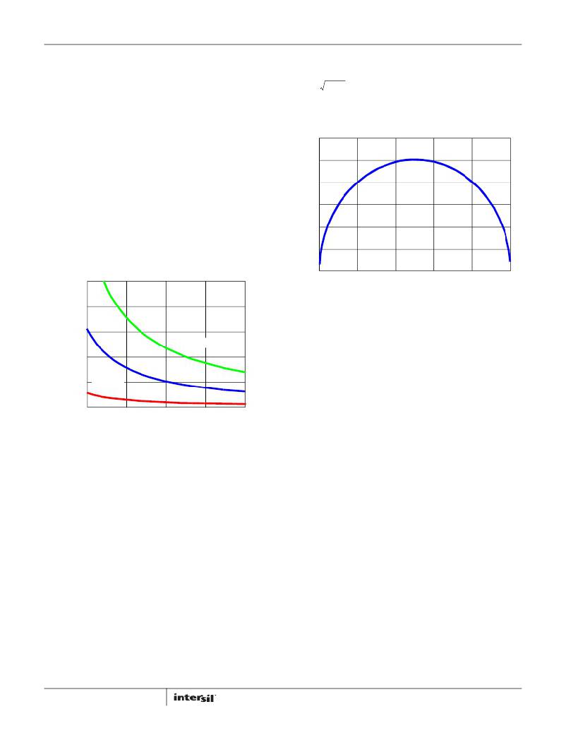
�The� input� ripple� current� is� graphically� represented� in� Figure� 45.�
�V� OUT� 2� *� (� V� OUTMAX� ?� V� OUT� )� 2� –� 1� )�
�I� OUT� 2� *� L�
�C� OUT� =� -------------------------------------------------------------------------------------�
�(EQ.� 8)�
�0.6�
�0.5�
�where� V� OUTMAX� /V� OUT� is� the� relative� maximum� overshoot�
�allowed� during� the� removal� of� the� load.� For� an� overshoot� of� 5%,�
�0.4�
�V� OUT� 2� *� (� 1.05� 2� –� 1� )�
�the� equation� becomes:�
�I� OUT� 2� *� L�
�C� OUT� =� ----------------------------------------------------�
�(EQ.� 9)�
�0.3�
�0.2�
�The� graph� in� Figure� 44� shows� the� relationship� of� C� OUT� and� %�
�overshoot� at� 3� different� output� voltages.� L� is� assumed� to� be� 7μH�
�0.1�
�and� I� OUT� is� 3A.�
�0�
�0�
�0.2�
�0.4�
�0.6�
�0.8�
�D�
�FIGURE� 45.� I� RMS� /I� O� vs� DUTY� CYCLE�
�80�
�A� minimum� of� 10μF� ceramic� capacitance� is� required� on� each� VIN�
�60�
�40�
�20�
�12V� OUT�
�5V� OUT�
�3.3V� OUT�
�pin.� The� capacitors� must� be� as� close� to� the� IC� as� physically�
�possible.� Additional� capacitance� may� be� used.�
�Loop� Compensation� Design�
�ISL85033� uses� a� constant� frequency� current� mode� control�
�architecture� to� achieve� simplified� loop� compensation� and� fast�
�loop� transient� response.�
�0�
�1.02�
�1.04�
�1.06�
�1.08�
�1.10�
�The� compensator� schematic� is� shown� in� Figure� 47.� As� mentioned�
�in� the� COUT� selection,� ISL85033� allows� the� usage� of� low� ESR�
�V� OUTMAX� /V� OUT�
�FIGURE� 44.� C� OUT� vs� OVERSHOOT� V� OUTMAX� /V� OUT�
�Current� Sharing� Configuration�
�In� current� sharing� configuration,� FB1� is� connected� to� FB2,� EN1� to�
�EN2,� COMP1� to� COMP2� and� VOUT1� to� VOUT2� as� shown� in�
�Figure� 3.� As� a� result,� the� equivalent� gm� doubles� its� single�
�channel� value.� Since� the� two� channels� are� out-of-phase,� the�
�output� capacitor.� Choice� of� the� loop� bandwidth� f� c� is� somewhat�
�arbitrary� but� should� not� exceed� 1/4� of� the� switching� frequency.�
�As� a� starting� point,� the� lower� of� 100kHz� or� 1/6� of� the� switching�
�frequency� is� reasonable.� The� following� equations� determine�
�initial� component� values� for� the� compensation,� allowing� the�
�designer� to� make� the� selection� with� minimal� effort.� Further� detail�
�is� provided� in� “Theory� of� Compensation”� on� page� 20� to� allow� fine�
�tuning� of� the� compensator.�
�Compensation� resistor� R1� is� given� by� Equation� 11:�
�g� m� V� FB�
�frequency� will� be� 2X� the� channel� switching� frequency.� Ripple�
�current� cancellation� will� reduce� the� ripple� current� seen� by� the�
�output� capacitors� and� thus� lower� the� ripple� voltage.� This� results�
�in� the� ability� to� use� less� capacitance� than� would� be� required� by� a�
�single� phase� design� of� similar� rating.� Ripple� current� cancellation�
�also� reduces� the� ripple� current� seen� at� the� input� capacitors.�
�2� π� f� c� V� o� C� o� R� T�
�R� 1� =� ---------------------------------�
�which� when� applied� to� ISL85033� becomes:�
�R� 1� [� k� Ω� ]� =� 0.008247� ?� f� c� ?� V� o� ?� C� o�
�(EQ.� 11)�
�(EQ.� 12)�
�Input� Capacitor� Selection�
�To� reduce� the� resulting� input� voltage� ripple� and� to� minimize� EMI� by�
�where� C� o� is� the� output� capacitor� value� [μF],� f� c� =� loop� bandwidth�
�[kHz]� and� V� o� is� the� output� voltage� [V].�
�C� o� � V� o� � (� 10� )�
�C� o� � R� c� � (� 10� )�
�I� o� � R� 1�
�C� 1� =� ----------------------------------------� ,� C� 2� =� ----------------------------------------�
�forcing� the� very� high� frequency� switching� current� into� a� tight� local� loop,�
�an� input� capacitor� is� required.� The� input� capacitor� must� have� adequate�
�ripple� current� rating� which� can� be� approximated� by� the� Equation� 10.�
�Compensation� capacitors� C1� [nF],� C2� [pF]� are� given� by�
�Equation� 13:�
�3� 6�
�R� 1�
�(EQ.� 13)�
�19�
�FN6676.6�
�February� 23,� 2012�
�发布紧急采购,3分钟左右您将得到回复。
相关PDF资料
MIC5891BWM
IC DRVR LATCH 8BIT SER IN 16SOIC
MIC5891BN
IC DRVR LATCH 8BIT SER IN 16DIP
TAAB336K010G
CAP TANT 33UF 10V 10% AXIAL
SPX385AS-L-1-2
IC VREF SHUNT PREC 1.235V 8SOICN
A9AAT-1105F
FLEX CABLE - AFE11T/AF11/AFE11T
TDC225K025NSE
CAP TANT 2.2UF 25V 10% RADIAL
MIC5841BWM TR
IC DRVR LATCH 8BIT SER IN 18SOIC
SPX432AM-L
IC VREF SHUNT PREC ADJ SOT-23-3
相关代理商/技术参数
ISL85033IRTZ
功能描述:IC REG BUCK SYNC ADJ 3A 28TQFN RoHS:是 类别:集成电路 (IC) >> PMIC - 稳压器 - DC DC 开关稳压器 系列:- 产品培训模块:Lead (SnPb) Finish for COTS
Obsolescence Mitigation Program 标准包装:2,500 系列:- 类型:降压(降压) 输出类型:两者兼有 输出数:1 输出电压:5V,1 V ~ 10 V 输入电压:3.5 V ~ 28 V PWM 型:电流模式 频率 - 开关:220kHz ~ 1MHz 电流 - 输出:600mA 同步整流器:无 工作温度:-40°C ~ 125°C 安装类型:表面贴装 封装/外壳:16-SSOP(0.154",3.90mm 宽) 包装:带卷 (TR) 供应商设备封装:16-QSOP
ISL85033IRTZ-T
功能描述:IC REG BUCK SYNC ADJ 3A 28TQFN RoHS:是 类别:集成电路 (IC) >> PMIC - 稳压器 - DC DC 开关稳压器 系列:- 产品培训模块:Lead (SnPb) Finish for COTS
Obsolescence Mitigation Program 标准包装:2,500 系列:- 类型:降压(降压) 输出类型:两者兼有 输出数:1 输出电压:5V,1 V ~ 10 V 输入电压:3.5 V ~ 28 V PWM 型:电流模式 频率 - 开关:220kHz ~ 1MHz 电流 - 输出:600mA 同步整流器:无 工作温度:-40°C ~ 125°C 安装类型:表面贴装 封装/外壳:16-SSOP(0.154",3.90mm 宽) 包装:带卷 (TR) 供应商设备封装:16-QSOP
ISL85033IRTZ-T7A
功能描述:直流/直流开关调节器 3A STD BUCK REG - 4X 4 TQFN 250 PC REEL RoHS:否 制造商:International Rectifier 最大输入电压:21 V 开关频率:1.5 MHz 输出电压:0.5 V to 0.86 V 输出电流:4 A 输出端数量: 最大工作温度: 安装风格:SMD/SMT 封装 / 箱体:PQFN 4 x 5
ISL8505IRZ
制造商:Intersil Corporation 功能描述:PB-FREE DC TO DC POWER SWITCHING, 38LD QFN 5X7 - Rail/Tube
ISL8510EVAL1Z
功能描述:EVALUATION BOARD FOR ISL8510 RoHS:是 类别:编程器,开发系统 >> 评估板 - DC/DC 与 AC/DC(离线)SMPS 系列:- 产品培训模块:Obsolescence Mitigation Program 标准包装:1 系列:True Shutdown™ 主要目的:DC/DC,步升 输出及类型:1,非隔离 功率 - 输出:- 输出电压:- 电流 - 输出:1A 输入电压:2.5 V ~ 5.5 V 稳压器拓扑结构:升压 频率 - 开关:3MHz 板类型:完全填充 已供物品:板 已用 IC / 零件:MAX8969
ISL8510IRZ
功能描述:IC REG DL BUCK/LINEAR 24-QFN RoHS:是 类别:集成电路 (IC) >> PMIC - 稳压器 - 线性 + 切换式 系列:- 标准包装:2,500 系列:- 拓扑:降压(降压)同步(3),线性(LDO)(2) 功能:任何功能 输出数:5 频率 - 开关:300kHz 电压/电流 - 输出 1:控制器 电压/电流 - 输出 2:控制器 电压/电流 - 输出 3:控制器 带 LED 驱动器:无 带监控器:无 带序列发生器:是 电源电压:5.6 V ~ 24 V 工作温度:-40°C ~ 85°C 安装类型:* 封装/外壳:* 供应商设备封装:* 包装:*
ISL8510IRZ-T
功能描述:IC REG DL BUCK/LINEAR 24-QFN RoHS:是 类别:集成电路 (IC) >> PMIC - 稳压器 - 线性 + 切换式 系列:- 标准包装:2,500 系列:- 拓扑:降压(降压)同步(3),线性(LDO)(2) 功能:任何功能 输出数:5 频率 - 开关:300kHz 电压/电流 - 输出 1:控制器 电压/电流 - 输出 2:控制器 电压/电流 - 输出 3:控制器 带 LED 驱动器:无 带监控器:无 带序列发生器:是 电源电压:5.6 V ~ 24 V 工作温度:-40°C ~ 85°C 安装类型:* 封装/外壳:* 供应商设备封装:* 包装:*
ISL85402EVAL1Z
制造商:Intersil Corporation 功能描述:ISL85402 EVAL BOARD1 - 20LD QFN - INPUT VOLTAGE 36V, 2.5A - Bulk